yfrobot
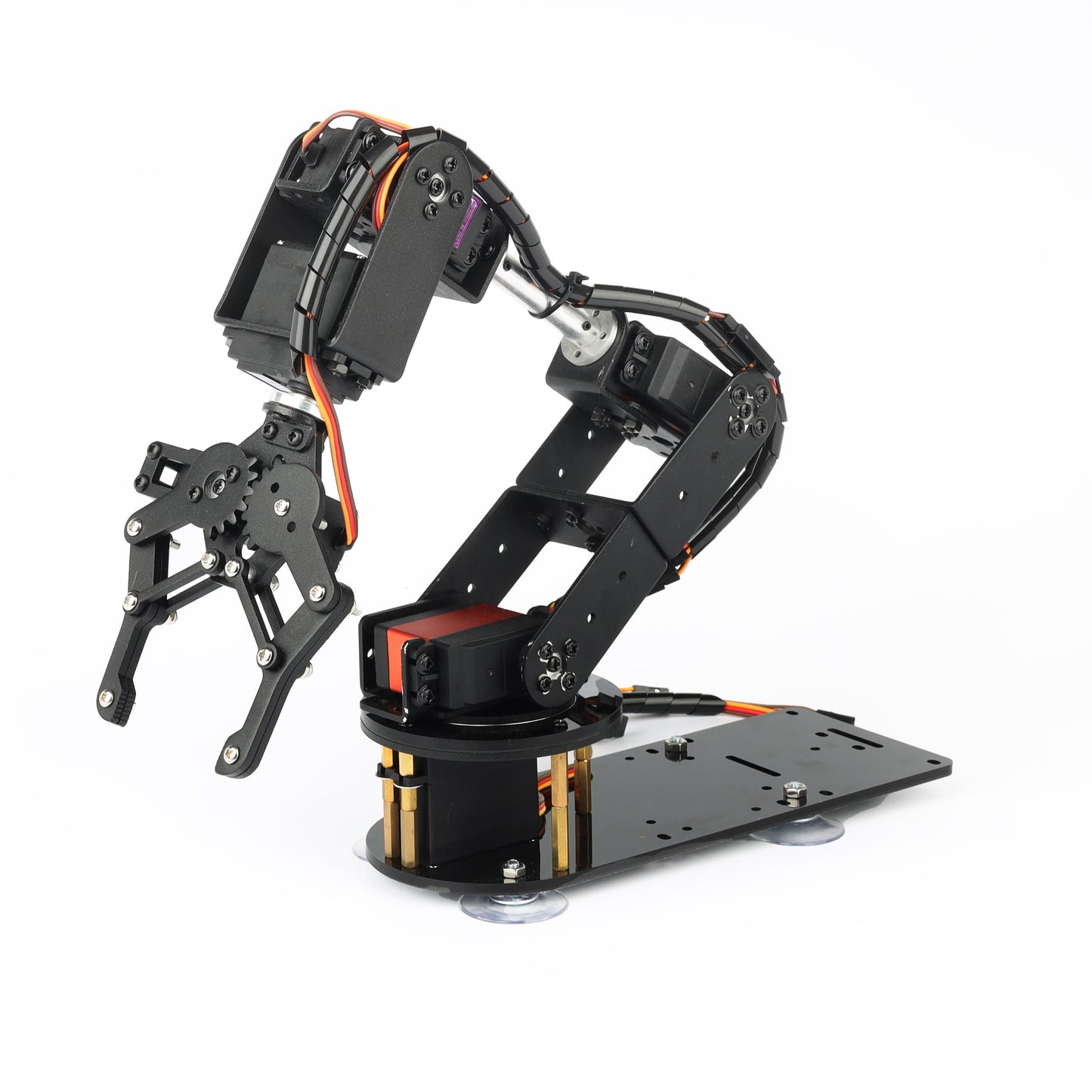
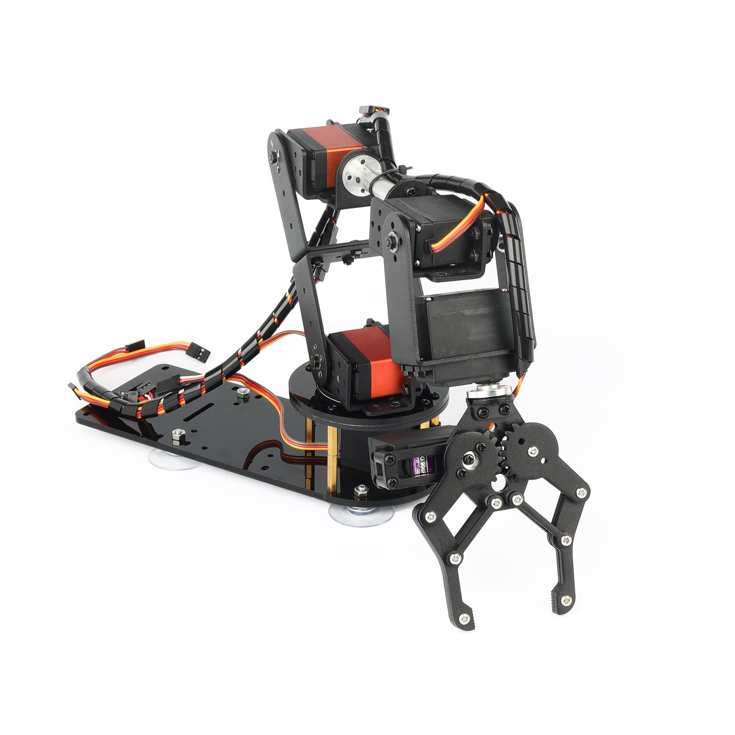
6DF robotic arm Disc base
6DF robotic arm Disc base
Couldn't load pickup availability
Overview:
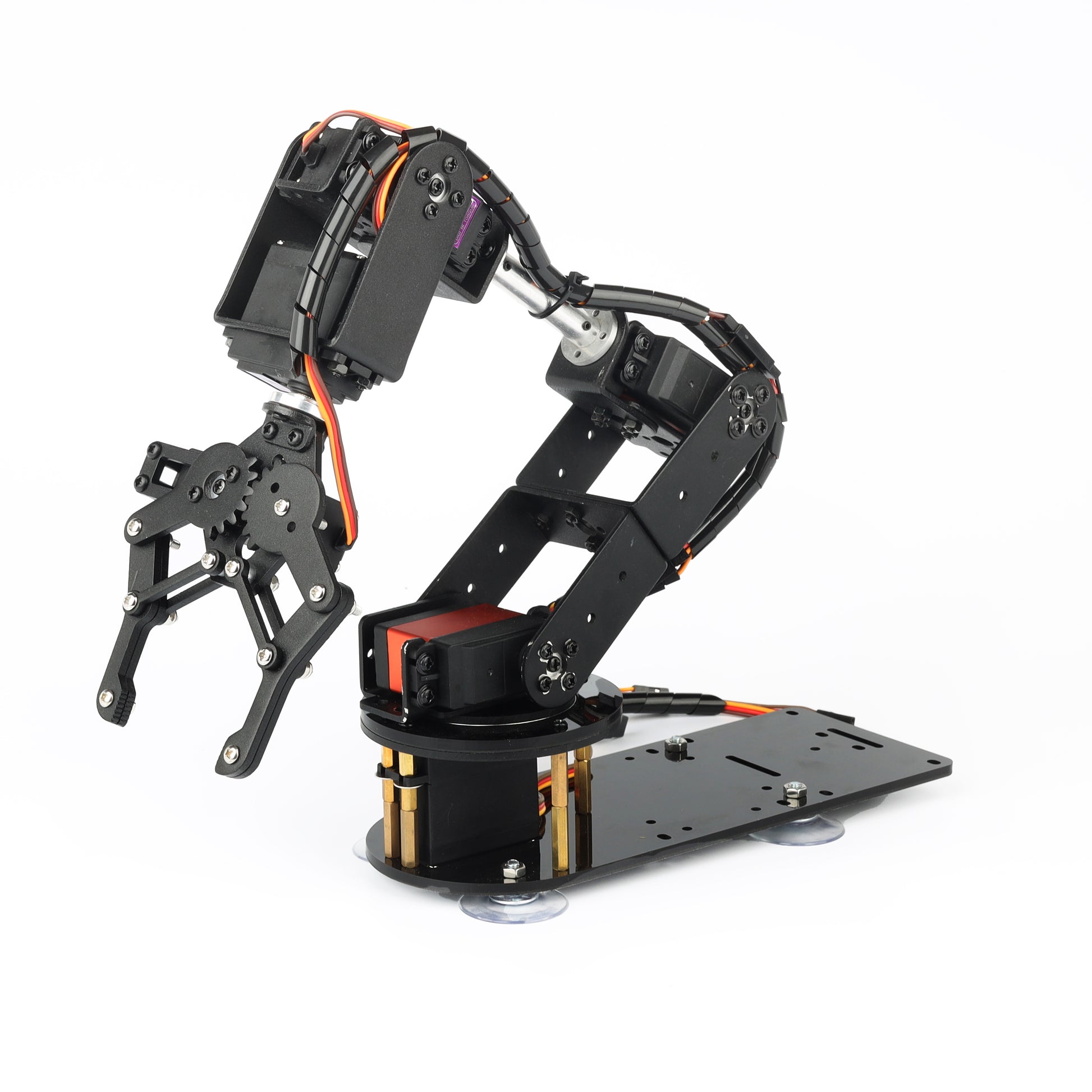
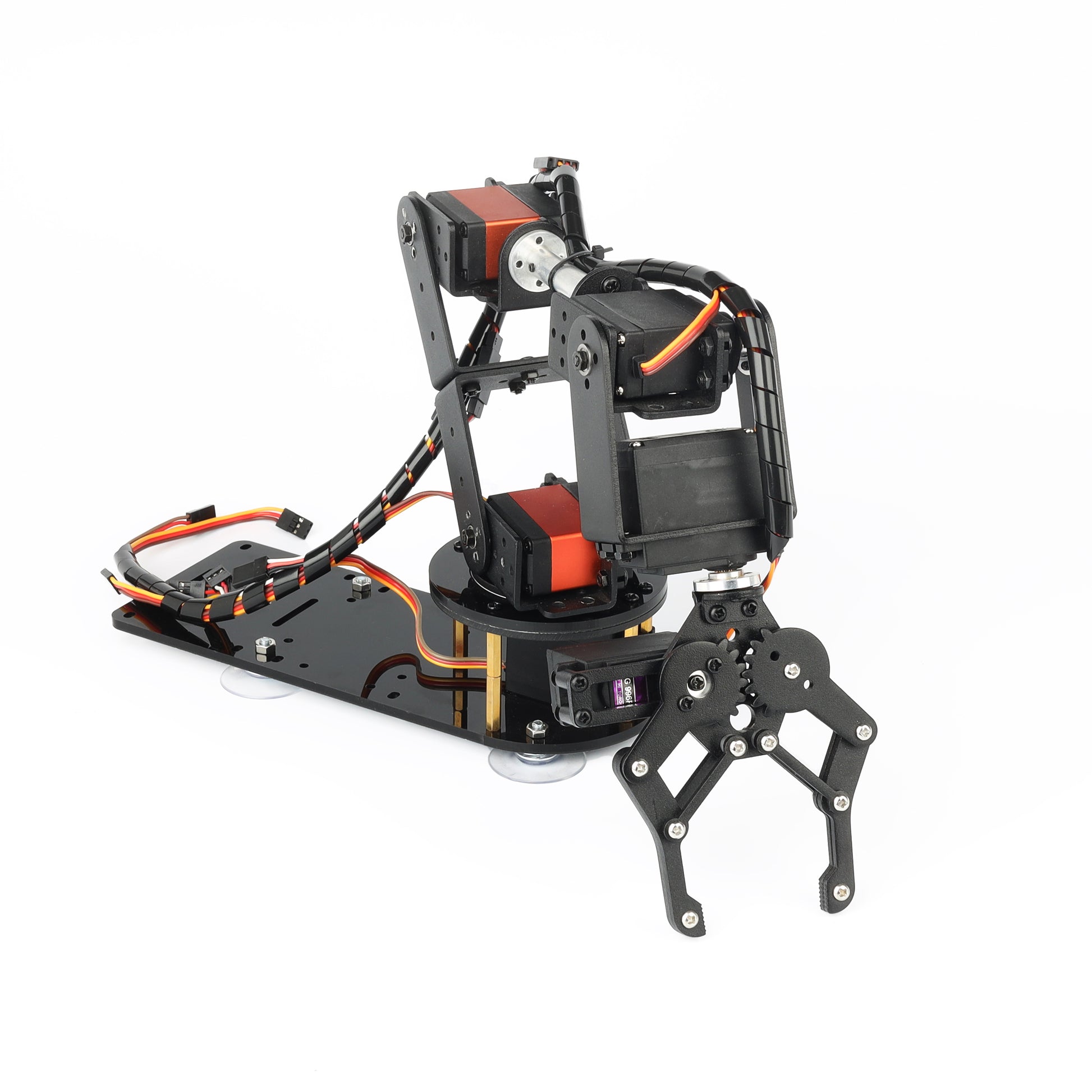
Six-degree-of-freedom machinery is widely used in the field of college teaching, personal IDY production and maker education, it can be regarded as a simple multi-degree-of-freedom demonstration platform, its power system is composed of 6 servo motors, can realize the demonstration of manipulator front and back, up and down and left and right grasping and handling.
The output of the metal servo is more stable, and the digital servo with high torque can also be selected. The steering joint adopts imported bearings, which can not only make the steering more flexible, but also make the steering of the servo in the same circle.
Dimensional parameters:

Specifications:
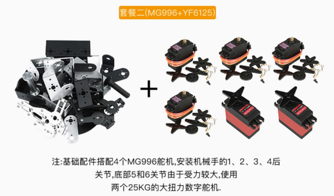
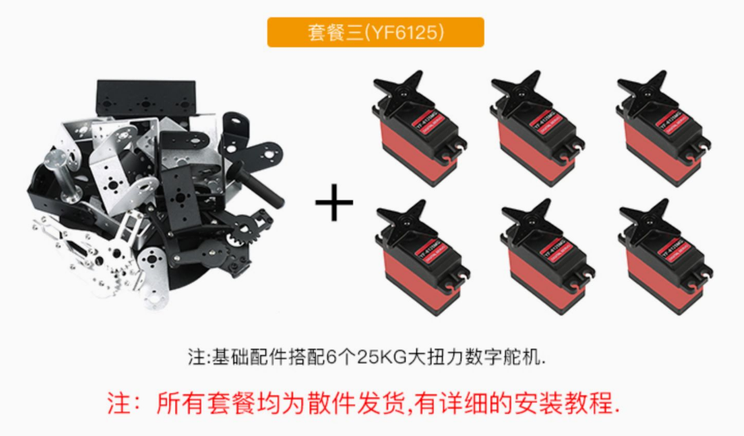
Tips: No matter which package you buy, there will be a slight jitter after the manipulator is installed, and the structure of the servo must not be compared with the stepper motor (the difference between different packages is that the quality and torque of the servo are different), and it is not recommended to buy it for high requirements. None of the packages have a control part and need to be purchased separately by the buyer
Introduction and principle of servo:
The control signal enters the signal modulation chip from the single-chip microcomputer port to obtain the DC bias voltage. There is a reference circuit inside, which compares the obtained DC bias voltage with the voltage of the potentiometer to obtain the voltage difference output, and the positive and negative output of the voltage difference is sent to the motor drive core to determine the positive and negative rotation of the motor. When the motor speed is constant, the potentiometer is driven to rotate through the cascade reduction gear, so that the voltage difference is 0, and the motor stops rotating.

The control signal enters the signal modulation chip from the single-chip microcomputer port to obtain the DC bias voltage. There is a reference circuit inside, which compares the obtained DC bias voltage with the voltage of the potentiometer to obtain the voltage difference output, and the positive and negative output of the voltage difference is sent to the motor drive core to determine the positive and negative rotation of the motor. When the motor speed is constant, the potentiometer is driven to rotate through the cascade reduction gear, so that the voltage difference is 0, and the motor stops rotating.



Introduce your content
Answer your customers' common questions
List a frequently asked question
Then provide an answer that will help your customer make an informed purchase.


