YFROBOT
YFROBOT Metal Gearmotor GP36 planetary gear deceleration DC brushed motor 12V with 13 CPR Encoder Hall speed measurement
YFROBOT Metal Gearmotor GP36 planetary gear deceleration DC brushed motor 12V with 13 CPR Encoder Hall speed measurement
Couldn't load pickup availability
Overview
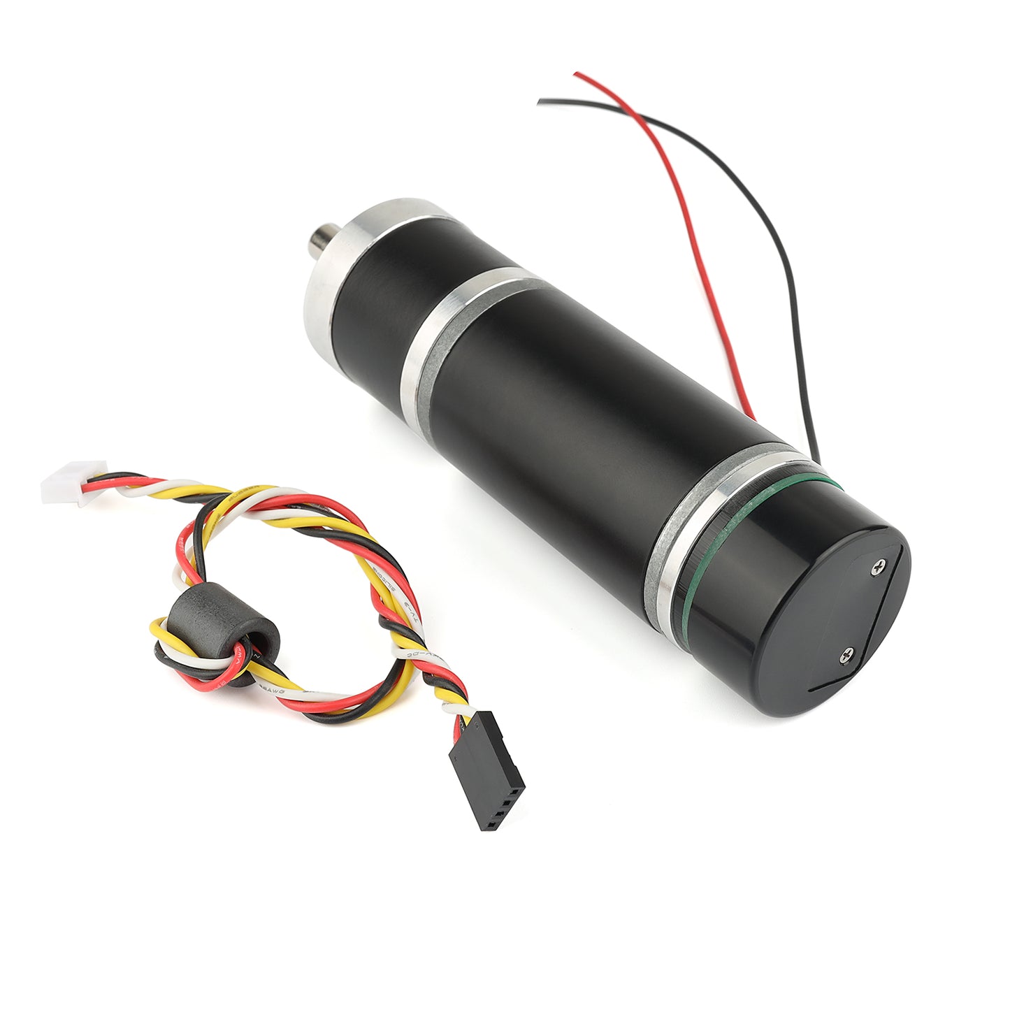
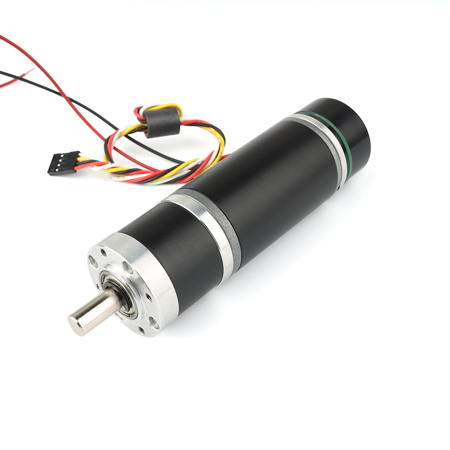
Measuring 36 mm (1.42inches) in diameter, these brushed DC gearmotors are the largest and most powerful we carry. all versions are available with integrated 64 CPR quadrature encoders on the motor shafts. The 12 V motors offer approximately the same performance at their respective nominal voltages. In general, these kinds of motors can run at voltages above and below the nominal voltages; lower voltages might not be practical, and higher voltages could start negatively affecting the life of the motor.The gearboxes are composed mainly of spur gears, but they feature helical gears for the first stage for reduced noise and improved efficiency:Its motor shaft is a 8mm D-shaft.
Using the Encoder
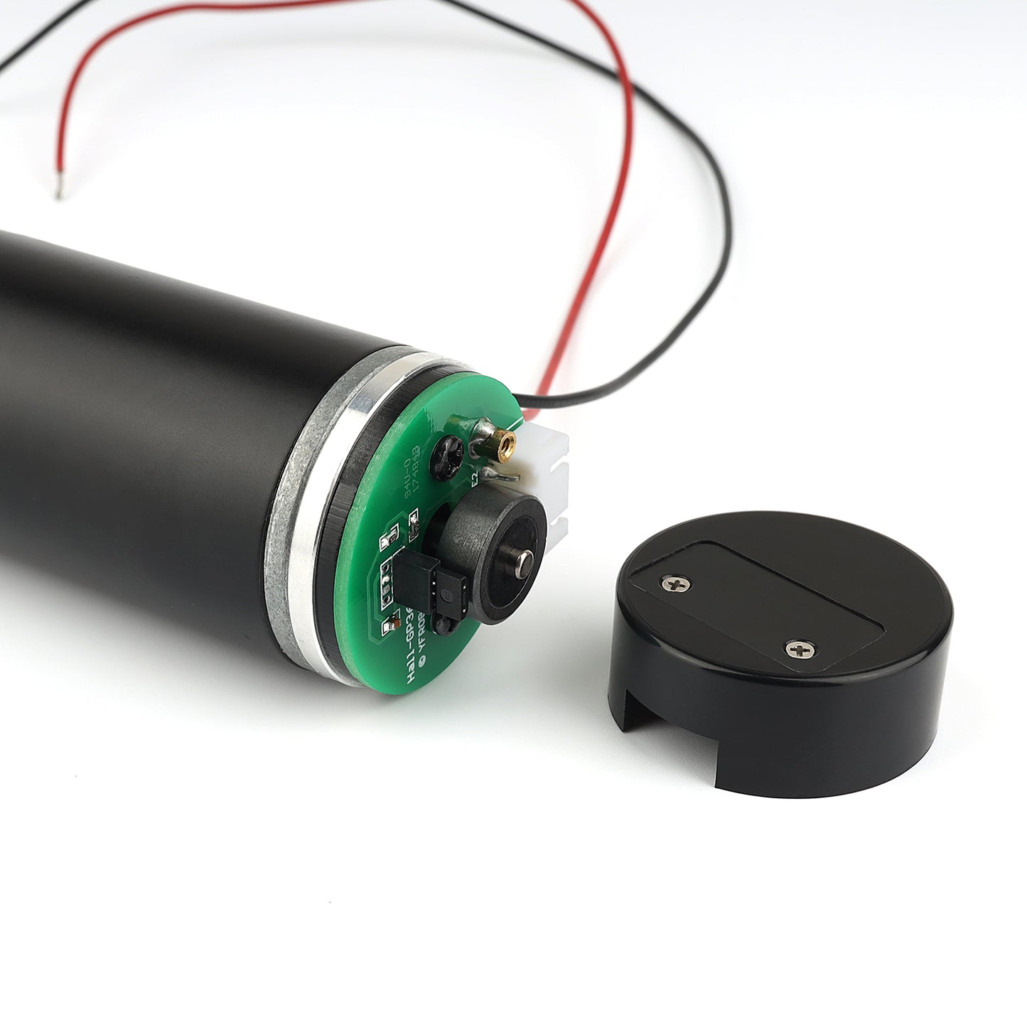
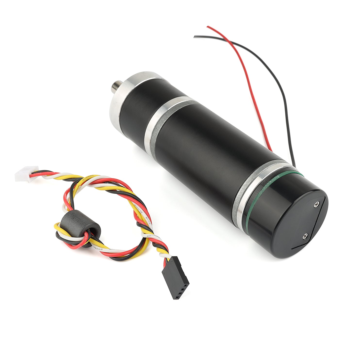
A two-channel Hall effect encoder is used to sense the rotation of a magnetic disk on a rear protrusion of the motor shaft. The quadrature encoder provides a resolution of 64 counts per revolution of the motor shaft when counting both edges of both channels. To compute the counts per revolution of the gearbox output, multiply the gear ratio by 64. The motor/encoder has six color-coded, 8″ (20 cm) leads terminated by a 1×6 female header with a 0.1″ pitch, as shown in the main product picture. This header works with. If this header is not convenient for your application, you can pull the crimped wires out of the header or cut the header off. The following table describes the wire functions:
| Color | Function |
|---|---|
| Red | motor power (connects to one motor terminal) |
| Black | motor power (connects to the other motor terminal) |
| Green | encoder GND |
| Blue | encoder Vcc (3.5 – 5 V) |
| Yellow | encoder A output |
| White | encoder B output |
The Hall sensor requires an input voltage Vcc between 3.5 and 20V, with a maximum current of 10 milliamps. The A and B outputs are square waves that are approximately 90° out of phase, with a voltage range of 0V to Vcc. The transition frequency tells you the speed of the motor, while the transition sequence tells you the direction.
The oscilloscope capture shown above displays the A and B (yellow and white) encoder outputs for a 12V motor and a 5V Hall sensor Vcc. By calculating the rising and falling edges of the A and B outputs, 52 counts are obtained for each motor shaft. Using a single edge from only one channel would result in 13 counts per motor shaft, so the frequency of the A output in the above oscilloscope capture is 13 times the rotational frequency of the motor.
Precautions
- This product does not have waterproof function, and it is strictly prohibited to use in water or damp environments.
- Short circuit between positive and negative poles is prohibited.
- Obtain information through email.
Motor parameters
|
Reduction Ratio |
DC Voltage (V) |
No-Load Speed (r/min) |
Load Speed (r/min) |
Rated Torque (kg.cm) |
Rated Current (mA) |
Stalled Torque (kg.cm) |
Stalled Current (mA) |
|
1:14 |
12 |
405 |
285 |
7.9 |
3000 |
60 |
7000 |
|
1:27 |
12 |
208 |
146 |
15.5 |
3000 |
60 |
7000 |
|
1:51 |
12 |
110 |
77 |
27.9 |
3000 |
60 |
7000 |
Electrical characteristics
|
Specification |
Symbol |
Test Condition |
Min |
Typical |
Max |
Unit |
|
Input Voltage |
Vcc |
-- |
2.7 |
5 |
5.5 |
V |
|
Output Saturation Voltage |
Vce(sat) |
VCC=14V; IC=20mA |
- |
300 |
700 |
mV |
|
Output Leakage Current |
Icex |
VCC=14V; VCC=14V |
- |
<0.1 |
10 |
A |
|
Input Current |
Ice |
VCC=20V, output open |
- |
5 |
10 |
mA |
|
Output Rise Time |
Tr |
VCC=14V; RH=820Ω;CH=20pF |
- |
0.3 |
1.5 |
S |
|
Output Fall Time |
Tr |
VCC=14V; RL=820Ω;CL=20pF |
- |
0.3 |
1.5 |
S |
|
Operating Temperature Range |
Topr |
|
0-85 |
℃ |
||


Introduce your content
Answer your customers' common questions
List a frequently asked question
Then provide an answer that will help your customer make an informed purchase.


